All Portable Discussion Zone build #4
Our fourth build project is something I was really excited to get into, and ended up spending an inordinate amount of time on. A transmatch, antenna tuner or ATU: Antenna Tuning Unit. I will try to be consistent in using transmatch. Part of the reason for choosing a transmatch is that it ties in directly with our SWR/Power meter build, as the purpose of a transmatch is to match the impedance of your radio to your antenna (hence transmatch: transmission-match), so the way you would set up your equipment is: [Transceiver]-[SWR bridge]-[Transmatch]-[Antenna]. The SWR bridge will tell you whether the Transceiver is seeing 50 Ohm, and the Transmatch can make this happen by means of an L/C network.
In talking about various aspects of transmatches we discussed my interest in small SWR bridges and basic matching units to squeeze two or three bands out of a single compact antenna element, and Adam K6ARK showed us the sub-miniature T-Match that he has been developing for low power work (Based on Barb WB2CBA’s design HERE). After discussing the different circuit architectures we thought to start with the GQRP Limerick Sudden ATU which is a Z-Match circuit. In talking with Steve G0FUW at GQRP, we found that his opinion is that the Z-Match works best with balanced line rather than coax-fed antenna systems, and that when working with coax the tuning notch is sharp and harder to find. G0FUW kindly offered his notes on building an L-Match using an air-wound inductor, which in turn was based on a Heathkit HFT-9. The L-Match network should be the most efficient design–in terms of RF and losses–for a coax-fed antenna system.
A few other resources that I found useful are the Sotabeams Adventure Tuner (discontinued), the Emtech ZM-2 manual, the ATL QRP Antenna Tuner by SP5JNW, QRP ATU by DF3OS and also the Hendricks SLT+.
Design considerations
Even though I have built two Z-Match units from kits (QRPguys and GQRP), I honestly have no understanding of how they work. Their main advantage is that the only adjustments are two variable capacitors, which means they can be “tuned” with the key down. Their apparent disadvantage is that they have a relatively sharp Q, so finding the “tune” is meant to be tricky, which is why we opted for an L-match in this build. An L-match is essentially two components, an inductor and a capacitor: to be adjustable we use a tapped inductor and a variable capacitor. The typical design has the inductor in series with the RF path, and the capacitor as a shunt to ground. The L-match is meant to be the “most efficient” design of transmatch, but has the disadvantage that it can only tune either a high impedance load or a low impedance load, but not both. If you have already looked at the PDFs above, you will notice that these are in fact T-match units, meaning that they have the unductor shunted to ground, and a series capacitor on either side of it: so a T-match is essentially two L-match tuners in opposite orientation to each other, arranged so that it can match both high and low impedance loads. The lore is that they are less efficient because one capacitor is somewhat redundant and may absorb some of your RF in any given scenario.
At this point in my understanding I found the Sotabeams Adventure Tuner, an L-match, which describes the simple practice of reversing the transceiver and antenna ports depending on the impedance of the load. And to do this, it’s peak current (output) beacon is placed near both antenna ports, one at either end of the circuit.
With all of this in mind, I decided that I was going to build an L-match with a tapped inductor, a switch to reverse the input and output for high and low impedance (something I did not find in any design I found online), and “RF present” LED, a “Peak output” LED and a 3 LED SWR bridge. To make the beacons all work correctly they need to be placed at the correct point in the circuit relative to the switch, input and output. The SWR bridge and beacon set up is somewhat based on the DF3OS transmatch, but more similar to the TinySWR which is based on his design, however both of these remain in-circuit and use a Stockton bridge to sample RF, whereas I wanted to be able to have a “tune” switch to protect the transceiver. This involves switching-in a dummy load so that the rig just sees 50 Ohm, but the matching network is connected to the SWR bridge. Typically this is done with a Wheatstone bridge which–in essence–has a dummy load across the switch and in series between the transceiver and the matching network, and off one leg there is a voltage divider that is used to sample voltage with a Shottky diode to drive an LED. On my first design I decided to build a hybrid pulled from KD1JV’s design in the SLT+, but with the LED ladder from the TinySWR. The “peak output” beacon comes from the Sotabeams design.
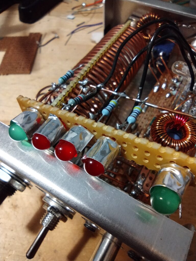
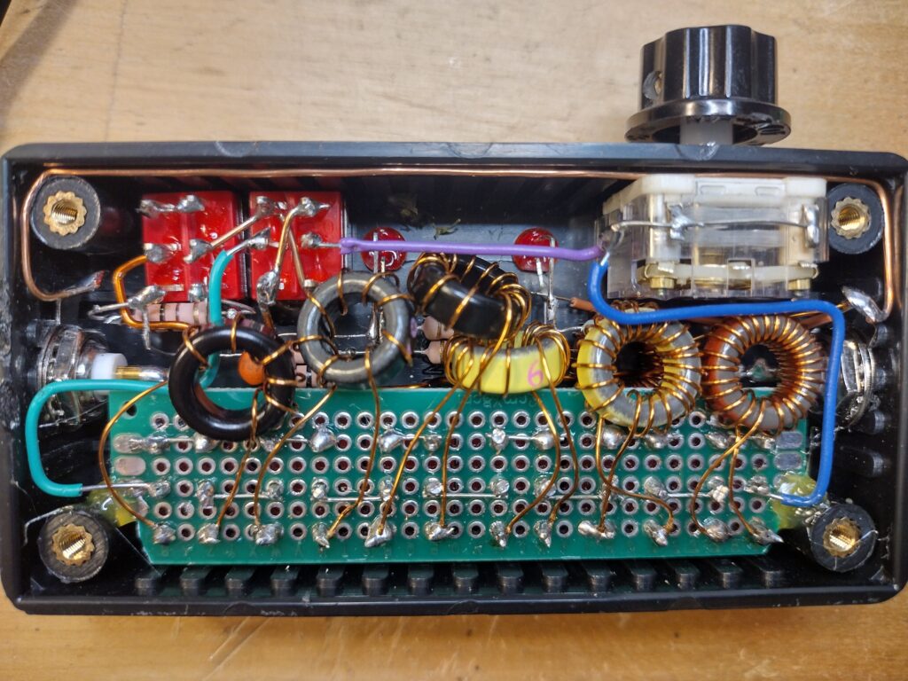
I found a case in my parts bins which came from Maplin over 20 years ago (Maplin being the UK equivalent of Radio Shack, which is no longer around): I think I had used it to house a power supply when I was at college, and it is a simple folded aluminium case. I started winding the coil from a copper core pulled from an offcut of ground wire, initially following the specs in the SP5JNW instructions. My wire was too stiff to stay firmly on my former, so I ended up using 3 strips of perfboard to space out the windings. I then soldered it onto the end of my rotary switch, axially, with the relevant taps. After an initial run of coax from the front of the case to the rear, I decided to replace them with a piece of stripboard to keep things more tidy. The components for the SWR gubbins could then be on a daughterboard above this. I ended up with one board to carry the wheatstone resistors, and a second one above this with the stockton and diodes. The resistors were all assembled on a ground rail behind the LEDs.
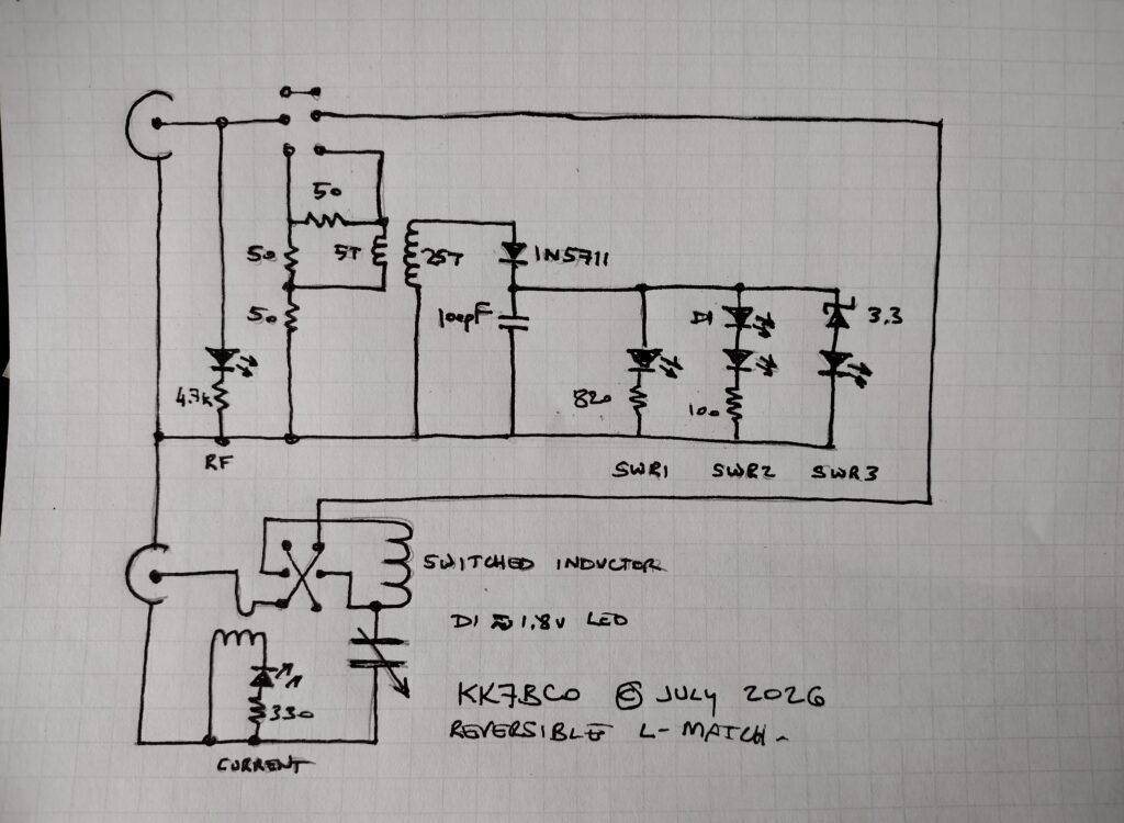
As you can see, the relative complexity of the SWR bridge greatly outweighs that of the matching network. I did end up adjusting the resistor values for the LEDs to make them a little more even, this was done by driving the ladder with a 9v PP3 battery, then trial and error. It is worth noting that the SWR1 LED does need to be one with low forward voltage, I used one around 1.8v. The others are less critical. The diode D1 that I used is an IR LED with a forward voltage around 1.7v, its purpose is to provide a fixed voltage drop over which SWR2 will glow. SWR3 starts above 3.3v (any Zener around 3v will work). The sensing diode will be decent with a 1N5711, a BAT or SD-101C, but it will also work with a 1N4148 as this is what the SLT+ uses. My Stockton bridge was wound on a T37-2, since that is what I had, 43 material is better. I ended up wrapping foil tape around the LEDs to keep them from bleeding light behind the panel. Also worth noting that I lost many hours troubleshooting nothing, as the shaft of the variable capacitor is electrically connected, so each time I would try to adjust it, things just didn’t behave the way I expected.
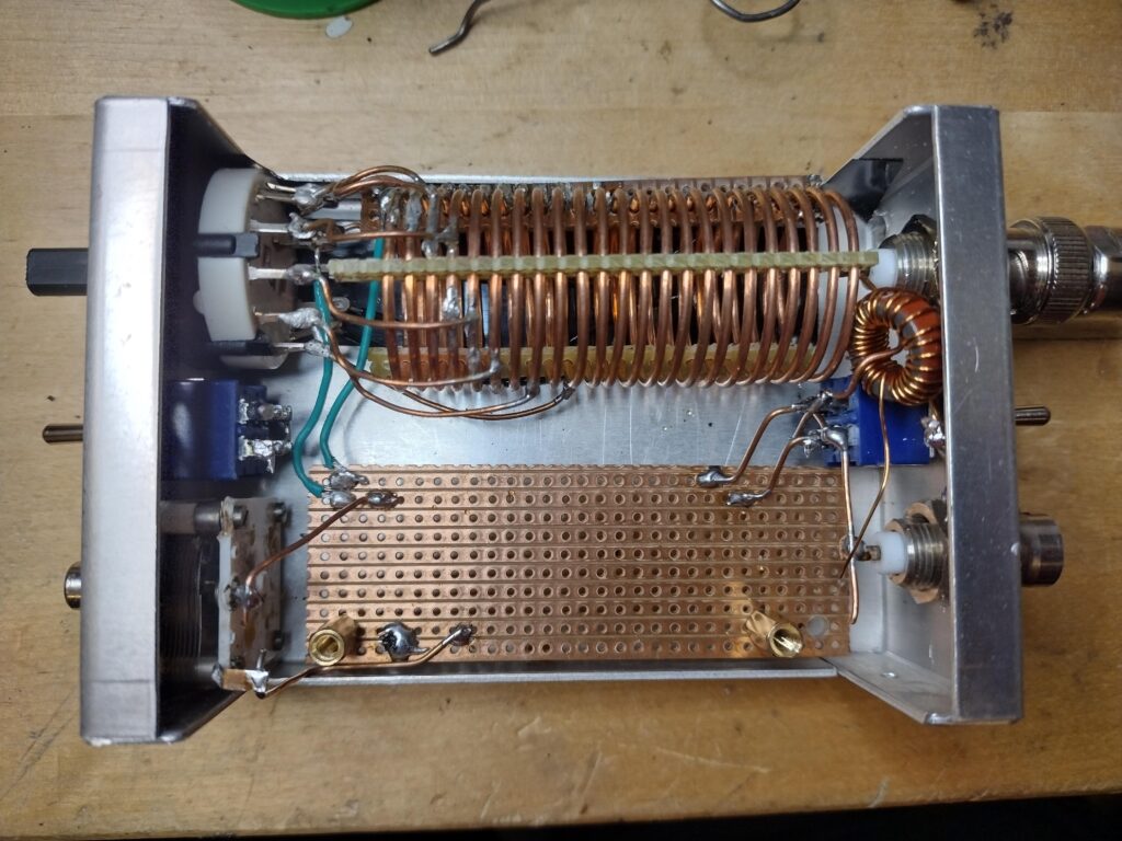
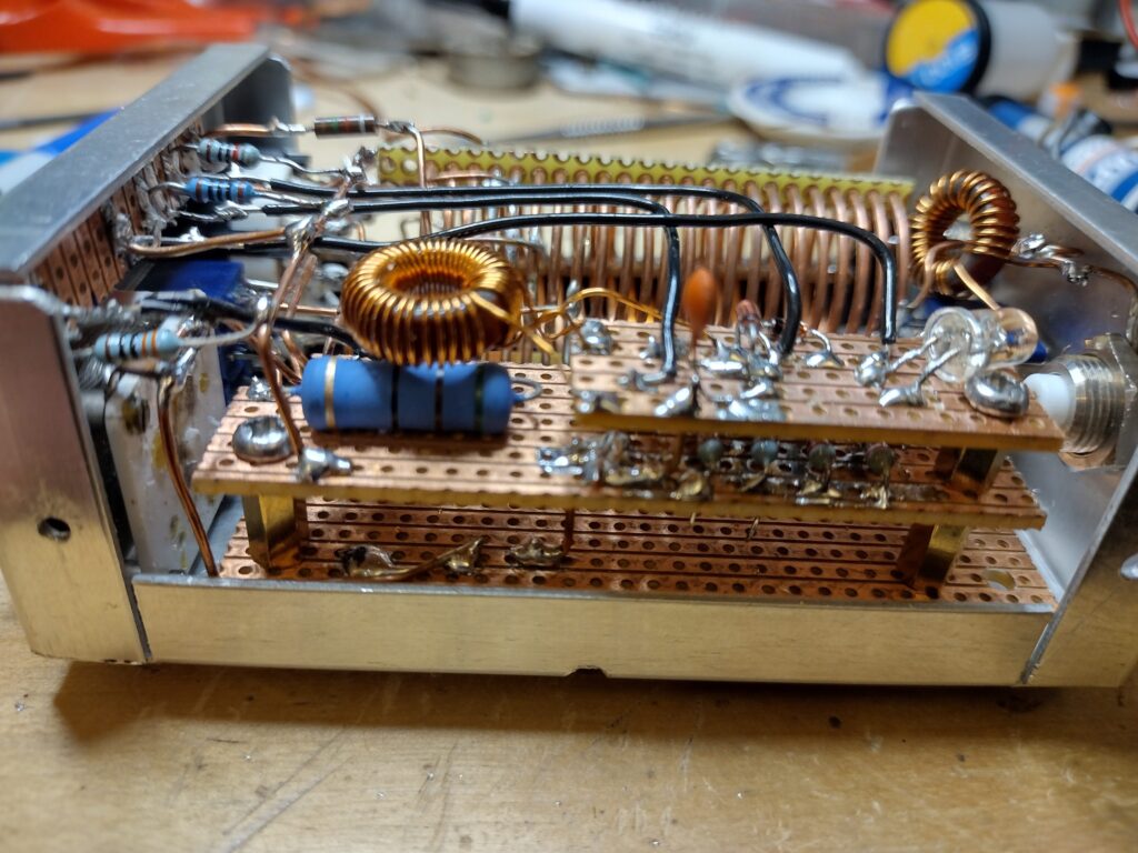
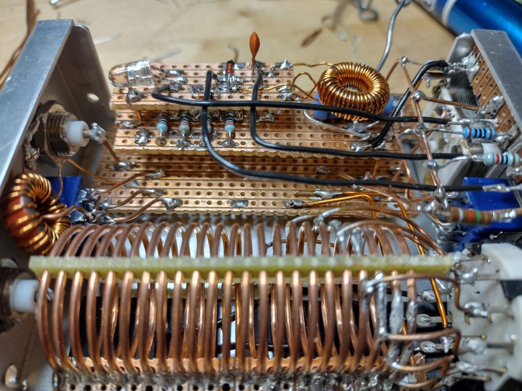
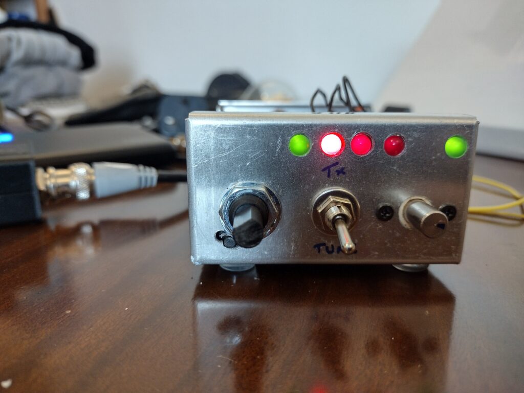
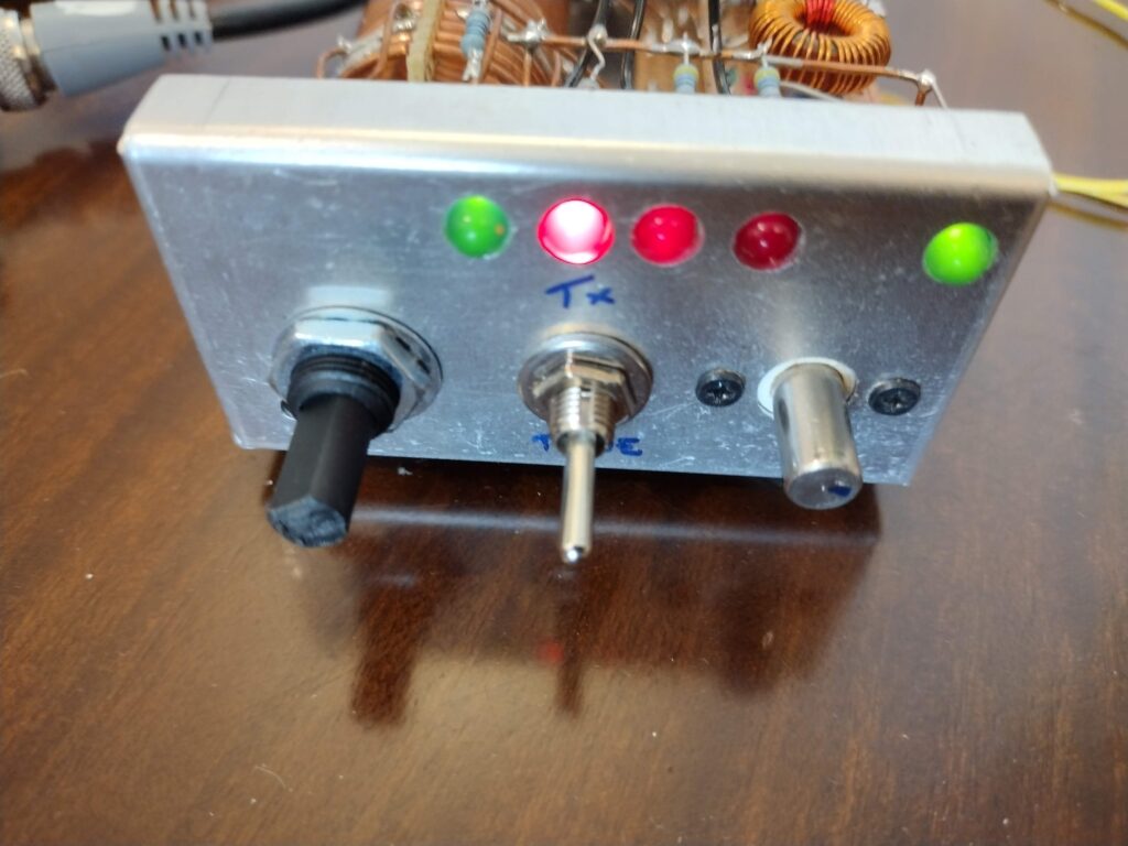
Version two.
After I built this, and whilst troubleshooting the LED ladder, I ended up building the GQRP Limerick Sudden ATU kit, which is an absolute pleasure to assemble, with good instructions. The transmatch is super easy to use as well, with a very reliable Wheatstone bridge. What I learned with this kit is that the 3 LED ladder does not–in fact–make it easier to find the impedance match.
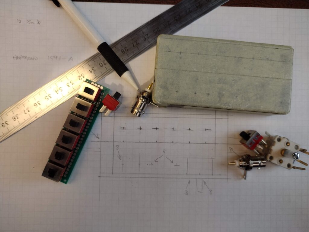
My next build ended up combinding my previous design with that of the Sotabeams Adventure Tuner. I had run out of 100R resistors, so I ordered a bunch of 1/2W carbon film, and a bunch of 1W metal film from Bitsbox, as well as a Hammond 1591ABK box, measuring 100x50x24.8mm external.
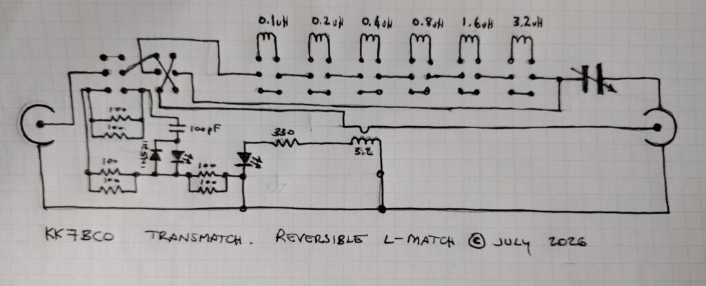
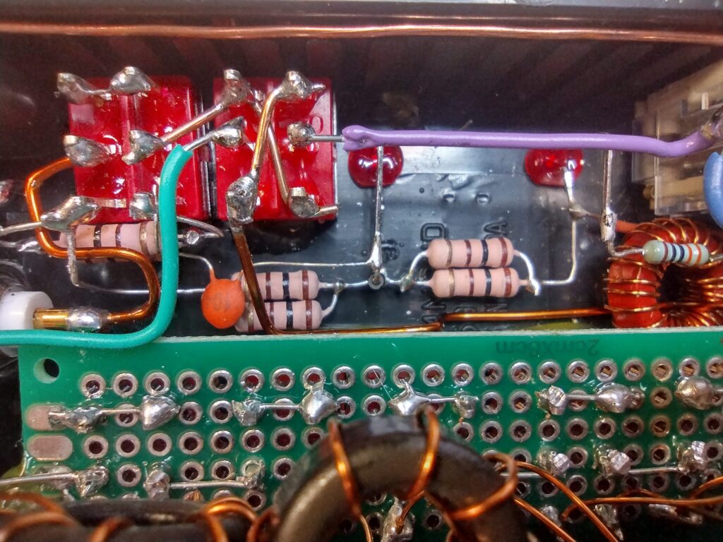
I got some switches off eBay that had a rating I thoght was sufficient, and crammed all of this into the little box. And here is where a poor judgement on my part took me on another journey of troubleshooting: I assumed that the dummy load 50 Ohm resistor was the only one that would see the full voltage from the transceiver, and that the divider could therefore have a lower rating, so my main load was 2x100R 1W metal film resistors in parallel, the divider was made from 2x100R 1/2w carbon film resistors. Under load the divider resistors would overheat almost instantly, and the bridge would stop working. The enclosure is too small for me to poke a finger in to figure out what is heating up and misbehaving, so it took me considerable time before I decided to swap these for the bigger metal film resistors. Metal film is also more stable at higher temperature, so much better suited to the application (lesson learned). Initially I also had put in two high brightness white LEDs which had a forward voltage of 3.3v, but these really refused to give me the dynamic range I needed to see them dimming, so I ended up replacing them with ordinary ~2v red LEDs.
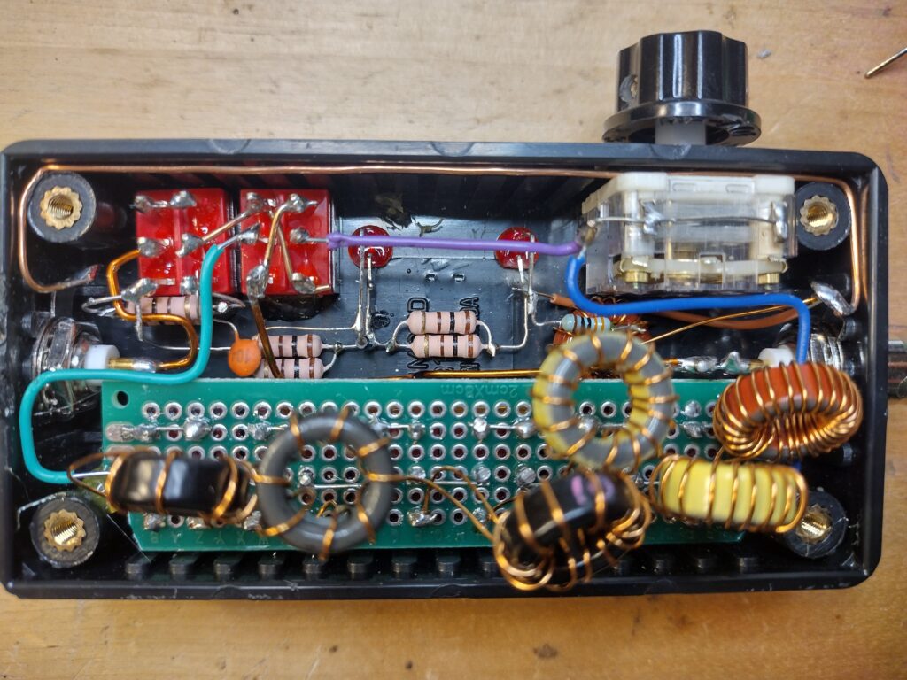
In our podcast recording yesterday, Adam K6ARK pointed out that the current rating of the switches is less critical than I had thought, since we tend to key-up before switching, so in the future I will try using much smaller switches which will afford me a lot of space in the case.
Both transmatch units work, and I think I have learned a lot from this project. I did struggle through most of both builds with the inexpensive soldering station that I have in my Edinburgh workshop, and ended up discovering the magic of leaded solder which flows at a much lower temperature. I ended up throwing in the towel, and after a few misses on eBay ended up with a Metcal, which is incredibly different to anything I have used before.
I am sure I will revisit this project in the future, but for now 73s.
Filed under: blog,Uncategorized - @ July 26, 2026 5:39 pm
Tags: antenna tuner, atu, diy, HAM radio, l-match, red summit rf, summits on the air, transmatch