Traps: An experimental SOTA vertical triband.
Traps are a divisive topic, with many hams saying they are inefficient, even though many commercial multi-band antennas use them. Whether they are inefficient or not, with portable operating there are many kinds of ways to measure efficiency:
Radiated power (or how much power is lost in the antenna)
Footprint (or how much space you need to have to put it up)
Speed of setup/breakdown
Ease of changing bands.
Radiated power is important when you have limited power. I often use 5w on SSB, so using an antenna that is only 30% efficient limits my reach beyon reason. My Off Centre Fed Dipole is pretty efficient, and works on multiple bands, but it works from 40m to 6m, and therefore needs a lot of space since it is a half wave on 40m. Again with the dipole, putting up a mast is not the fastest thing in the world, with guy lines, and the feed line wanting to tangle with the elements as you raise it. So 40m wire antennas on a mast take a lot of time and space, but can be very efficient, and can switch bands without modification.
Two popular vertical solutions are an adjustable loading coil on a slightly shortened whip, or a telescoping whip that can be set at different heights to cover different bands: These both are small in footprint and fast to erect, but they do kind of need an antenna analyser to make them resonant, which is not something I want to carry, nor spend the time doing. This is why I have been toying with the idea of a trapped vertical for 15-17-20m.
My project started last year when I purchased a military surplus AT-271B, a segmented 2.87m whip, which seems to be made of lightweight steel and brass. My plan was to build above this, adding traps and additional height to reach 15/17/20m for a quick deploy antenna. I met WA7ARK at Quartzfest in January, and he offered to help with some modeling. The full thread is HERE on QRZ.com.
So today, I shall start talking about traps.
First of all, it is the 15th of June 2026, and I do not recommend talking to GPT about it. Though it is able to make calculations, it seems to have no actual clarity on anything, and contraddicted itself multiple times, which was infuriating. Especially when–after several hours–I realised that I actually had all the information I needed already. So if you think you might have the information you need in a book, or a PDF, or you have read someone else’s post but you can’t find the bookmark, go look at those existing resources: finding them may be more efficient than taking the current “shortcut”.
A trap is an inductor and capacitor in parallel, which–when resonant–present a high impedance to RF. So, the first thing is that I want a trap to cut off my whip so that the 15m section is only seen above about 21.2MHz, and the rest of the whip is invisible: This means that I need to make a trap that is resonant just below the band I need, so that it does not interfere with the band with stray capacitance or inductance. So, I built a trap around 21MHz. I found this confusing, since in my mind I want about 3m of element to be used for 15m, so it would make sense for the high impedance to be above the band, but this is simply not how they work.
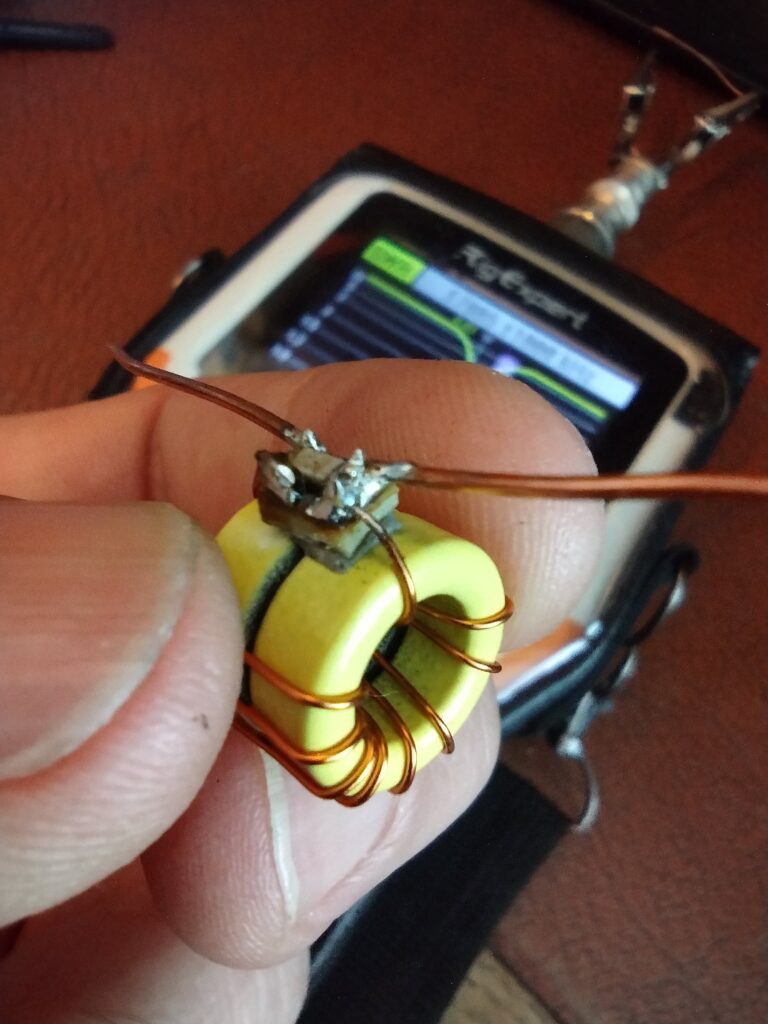
How do you build one? I wanted to make mine like the ones in big antennas, with mechanical objects as the capacitor and inductor, but I found that this was unrealistic at the scale I wanted to work with, so after some trial and error I decided to use 100pF surface mount caps, and two T50-6 cores stacked. How do you calculate values? WA7ARK calculated them in modeling software, but I recommend going over to the Sotabeams website and downloading their manual for their two trap designs. They have recommended values for the different bands and different power ratings. Since I was using the ferrite core from their 10w pico traps, but doubled up for higher power handling, the number of windings was off. However, their instructions on how to measure resonance are correct and very useful. Another good reference is Adam K6ARK’s video HERE, he also shows how to calculate rough windings, as well as measuring it with an antenna analyser.
I honestly wasted a considerable amount of time trying to figure out how to measure the L/C values and read the R/X values on the RigExpert, thinking that this was a more accurate or efficient way of doing it. But the GPT and the rest of the internet did not help, the data was misleading and returning to the RigExpert manual–seeing that they recommend using the SWR reading with a coupled wire–had me return to where I started, with instructions from Adam and Sotabeams.
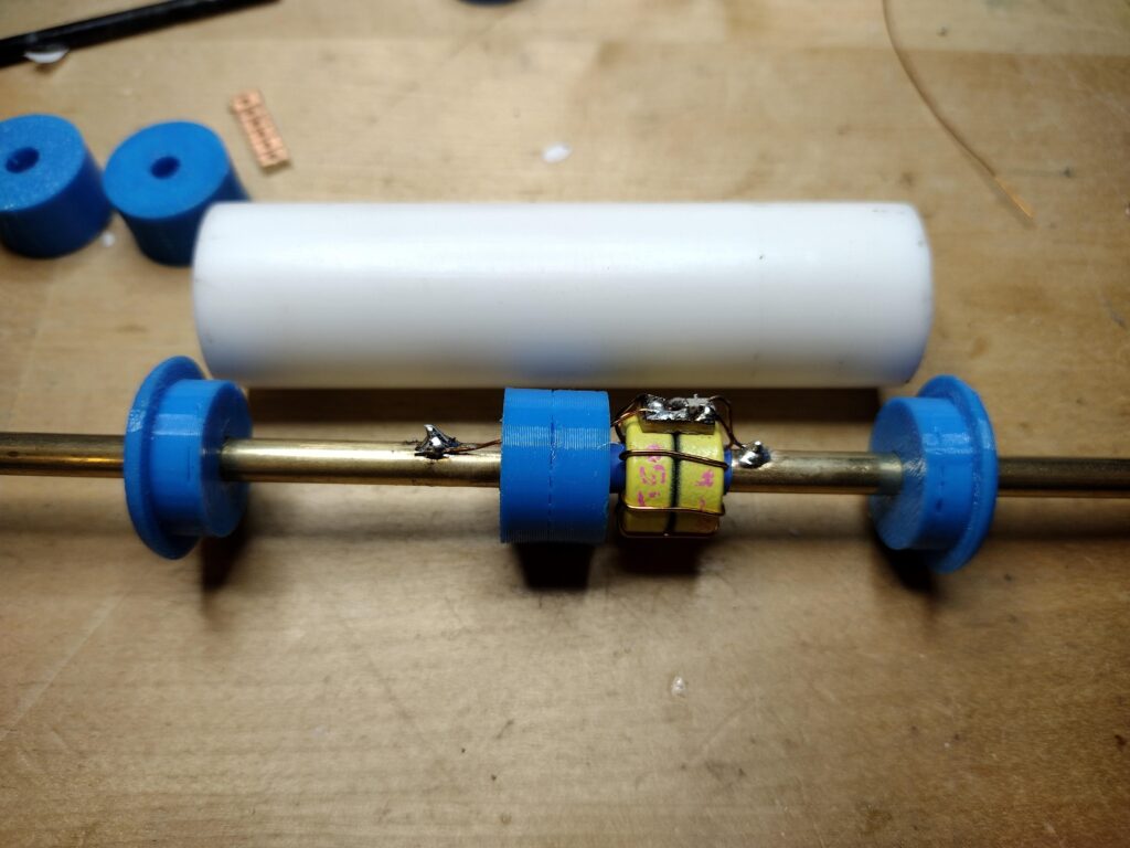
This is how the traps ended up being assembled. I 3d printed two end-caps and a spacer, which fit an 80mm section of 3/4″ PEX pipe. The middle section insulates the two bits of mast, and centres them in the outer sleeve to make a structure. It is pretty tidy, light and small.
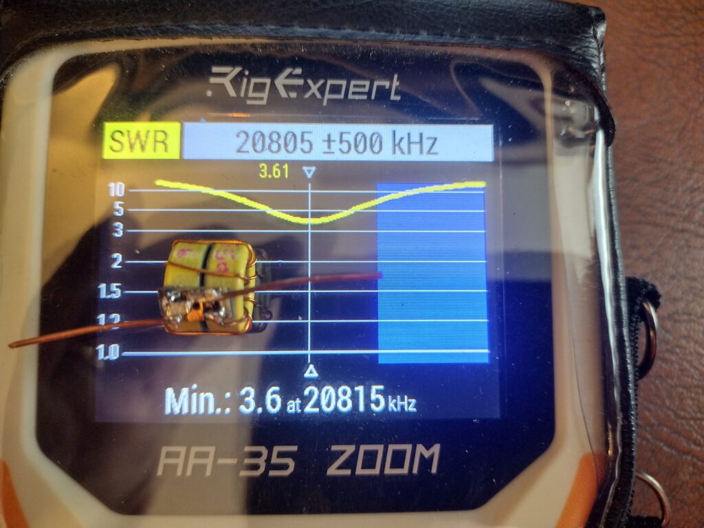
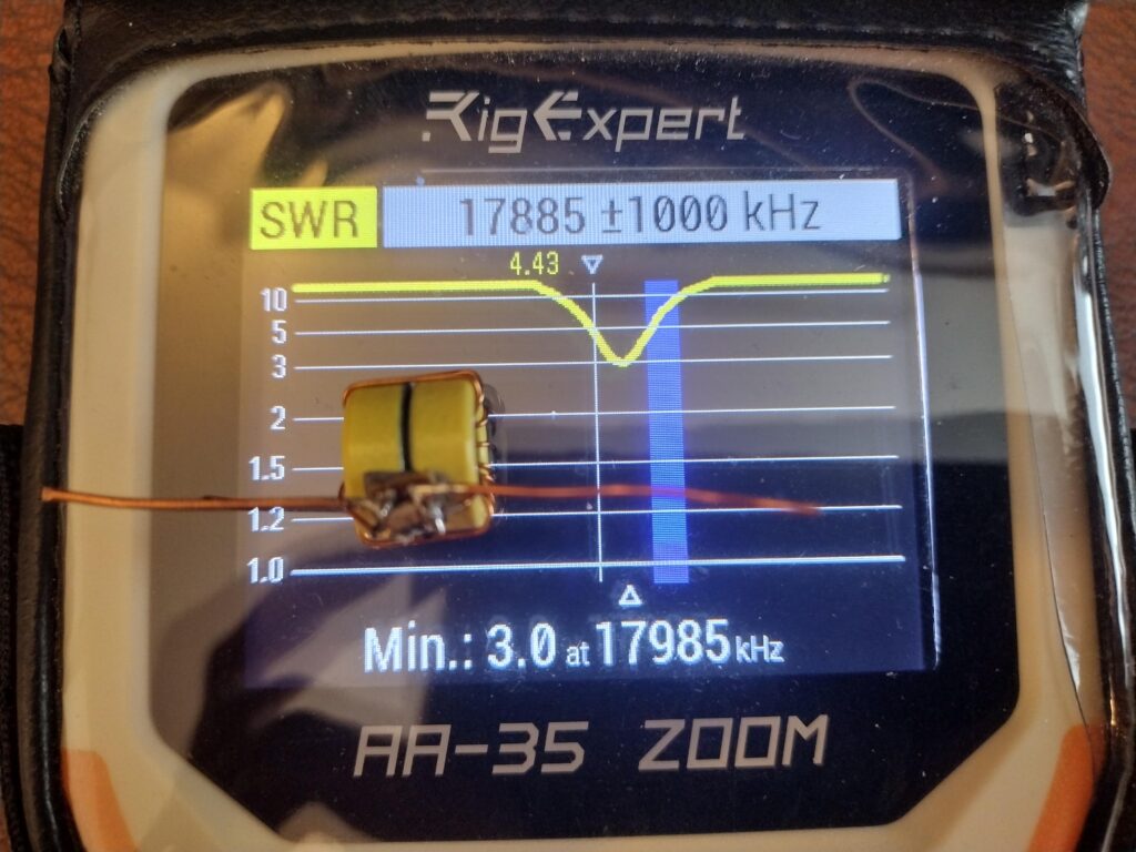
I took my first trap out to the park to put the analyser on it, with radials (6, one pair cut for each band as 1/4 wave). 15m and 17m were good with minor adjustment, dipping to around 1:1.5 SWR. Back in the workshop I built the second trap and subsequent antenna sections for 17 and 20m, and headed back to the park.
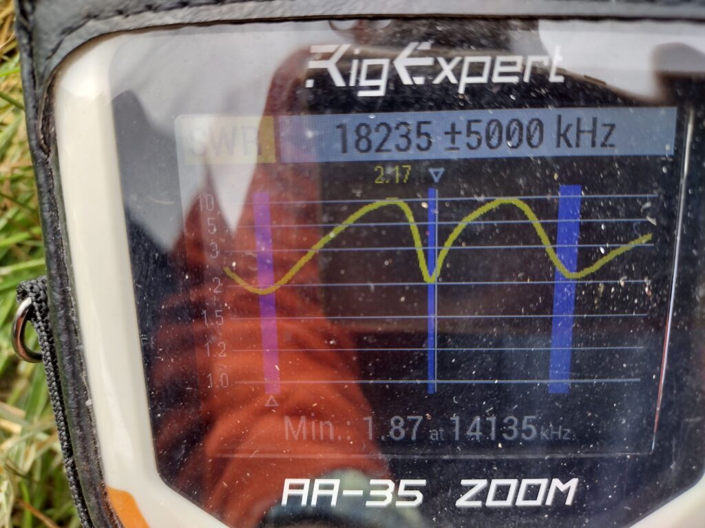
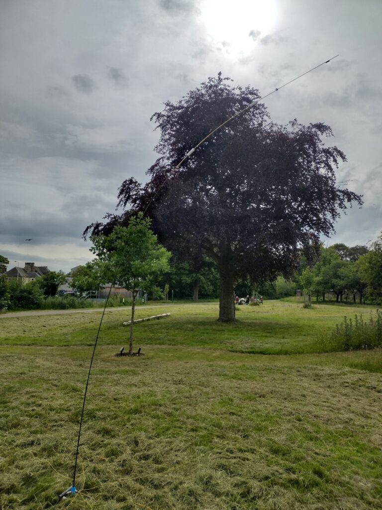
I am pretty happy with the plot: Traps work well, and the radial network I made is acceptable. However, the materials I am working with are not suitable. With no wind at all, the antenna is leaning over quite precariously, and barely stays up with my Kryptonite D-lock on top of the tripod. I am pretty sure that a slight wind would fold one of the upper sections under its own weight.
As a proof of concept, I have proof of half the concept, the electrical half. Element lenghts are a little shorter than the simulation showed, but there isn’t really any point in me recording these lengths when the antenna is too delicate to use. Maybe another six months of noodling will bring me to a structural solution that will be light weight and strong enough to exist under its own weight.
Until then, the project shall rest.
73
Filed under: blog,Uncategorized - @ June 16, 2026 5:54 pm