All Portable Discussion Zone build #3
Our third build project is a frequency counter. As I had found in my preliminary research, counting things is not easy. So, Charlie NJ7V was able to borrow part of a design and some parts as a component kit from Rex Harper W1REX at QRPme.com, you can order the parts HERE. Rex also joined Charlie and Adam to discuss how the circuit actually works, I highly recommend watching the discusson on youtube so you can see the schematic. The description of the discrete component parts of the circuit is really educational, and his understanding of the comparator and how injecting the realtime clock into the circuit to be able to count frequencies higher than the PIC’s capacity is enlightening.
I got my parts a couple of days before transitioning to my workshop in Edinburgh, and promptly got down to building. Rex provided almost all parts necessary, including a piece of copper clad board, and most importantly he provided the PIC which he programmed to do all of the magic. All I had to do was add some periferals like the LCD.
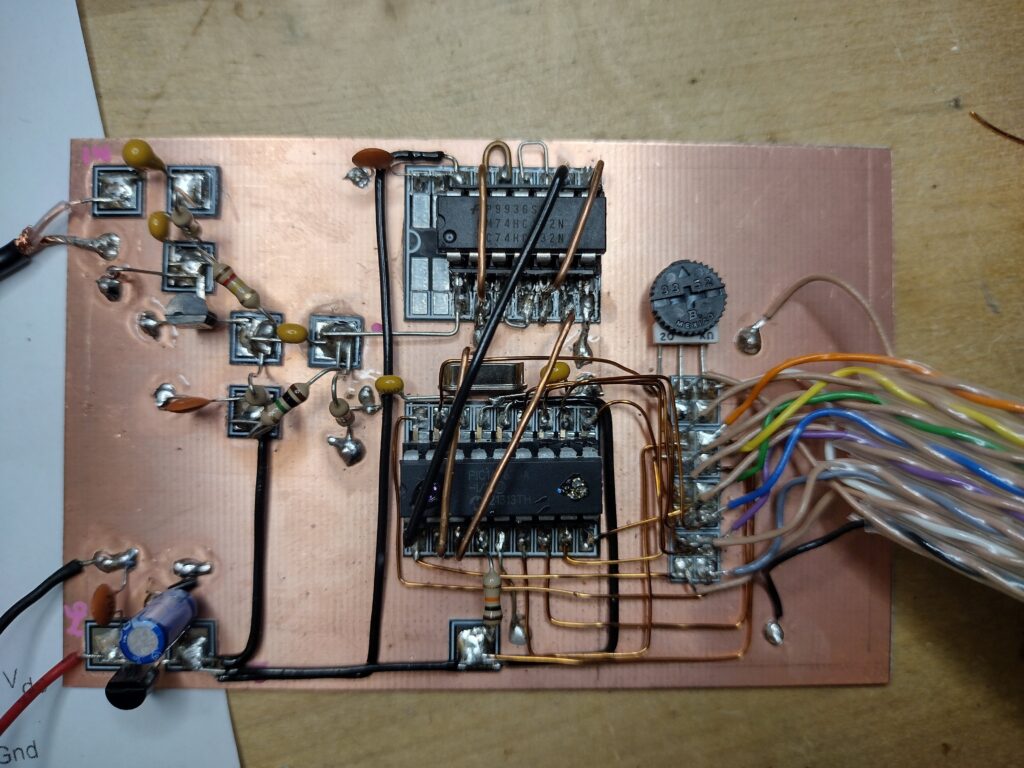
I started with the power regulator (bottom-left), which is a 5v regulator. Then I built the input circuit (top-left) which Rex explains in the video as: an initial Tantalum capacitor to cut any DC voltage from the input, followed by an L/C filter. Then there is a single Shottky diode which rectifies the AC by removing the lower half of its sine, which is fed into a transistor which stabilises the input and makes it into a square wave by the way that it is biased. Following that, a voltage divider makes sure the input is at the correct voltage. The next part is where I might have got too excited and made life hard. I put all the bridges on top of the comparator and PIC, which meant that all the lines from the PIC to the LCD were a little fiddly to wire. When I initially powered it up, I found that I had forgot one of the power lines, so the LCD lit, but did not display anything. Fortunately it did not take me long to find my error. Rex’s two-sided MEpads are really nice, with one large pad on one side and 4 isolated pads on the other.
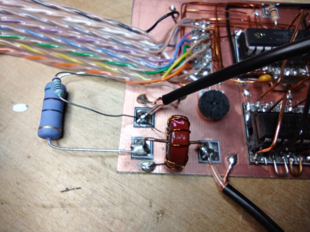
At this point I got to watch the chat with Rex, and realised that the input is expecting something in the region of 0.5Vac, but for the circuit to be useful I want it to be able to take input from a radio like the QMX which–at 5W RF–will be putting out a voltage near 13Vac. I thought to build an attenuator, but Adam suggested using a sampling tee, which is what we used in the Stockton bridge. A little research and I put 10t on a T50-2, found a 10 Ohm resistor and a 50 Ohm 5W resistor as a dummy load, this is what I made:
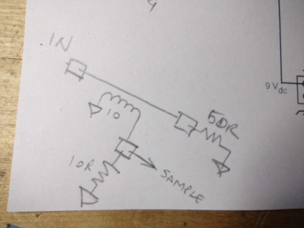
Sample goes straight back to the original input, IN is where I have my BNC. Accordingly this should be providing about -38dB attenuation, adding a rotary switch and other resistor values allows for different attenuation: 16 Ohm = -30dB, 50 Ohm = -20dB and 160 Ohm = -10dB.
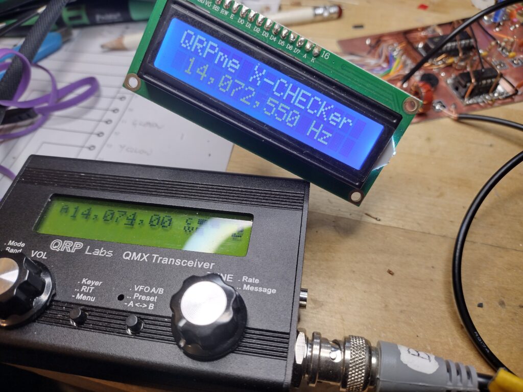
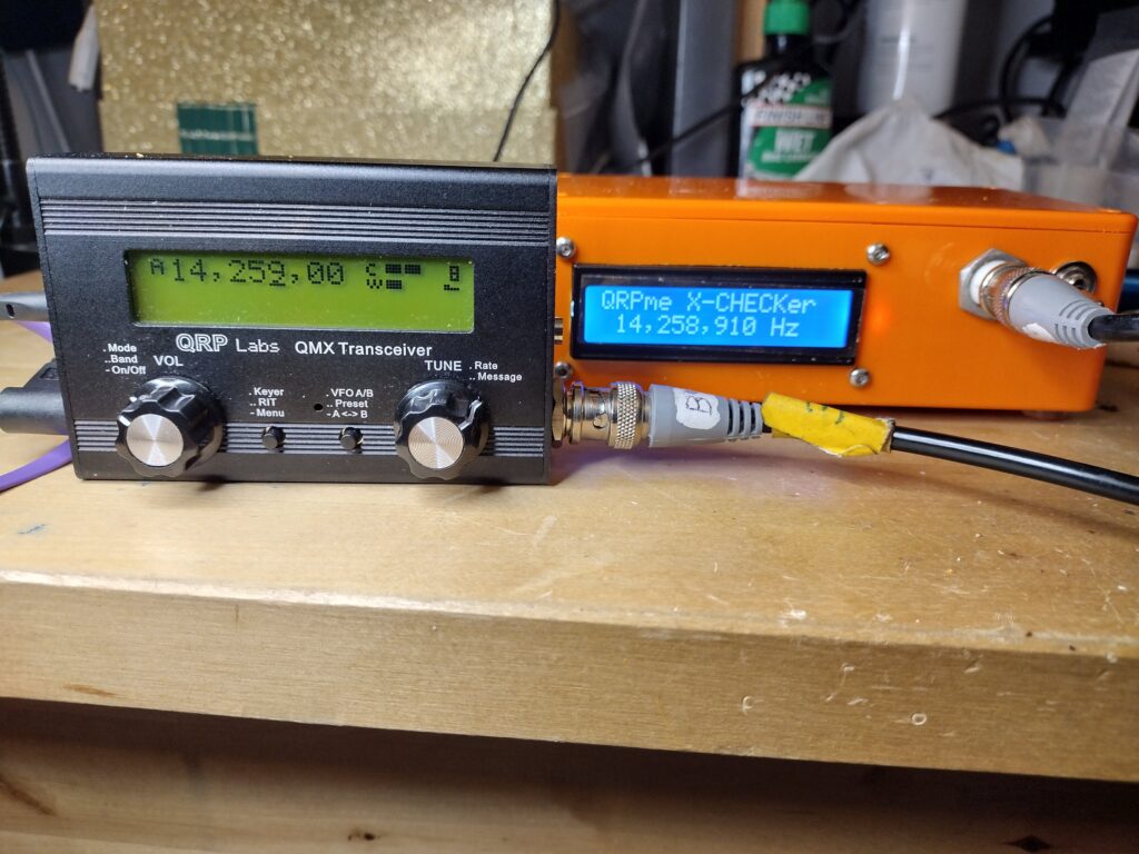
As you can see, the frequency is a little off. As Rex described, the schematic has a place for a variable capacitor to calibrate it. I popped a polyvaricon in temporarily, and I am seeing the need for about 300pF to align it with the QMX: This is more capacitance than expected, but sometimes the layup of the circuit, and how wires are dangling and paralleling introduces capacitance or even reactance to the circuit. Before moving the project into a permanent enclosure I will finalise this calibration and tidy up a few things. I am presently very pleased, as a couple of other little projects have not been going as well.
[12/6/26] After I wrote the above, I had some troubleshooting to deal with: the circuit stopped working, printing only a series of rectangles on the screen. Poking around and reading stuff I concluded this meant that the PIC was “on”, but not loading the patch: the oscilloscope was measuring 4.5v p-p square waves on several pins to the display. It turned out that the capacitors around the crystal, which is also related to the tuning, can inhibit the oscillation that runs the clock (this may be poorly described as my understanding is somewhat limited). After doing a lot of moving wiring around, I ended up re-flowing solder on the crystal and adding some capacitors to bring the readout closer to accurate, and it is now working. The oscilloscope shows very different signals when it is running, as they are digital, you will see a few spaced-out squares of different amplitude on the same line.
I found that the 5w dummy load does warm up pretty fast with the QMX, and that if the QMX is in SSB mode, the readout is variable, which may be to do with the attenuation in the sampling tee. Frequency still varies a few Hertz, but getting it more accurate than what you see in the picture was fiddly. It is good enough for now, and may end up getting modified for a specific purpose in the future.